
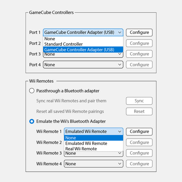
The Phob GameCube Controller offers competitive players many settings and options at their fingertips, so we’ve made this webpage to help users understand what the PhobGCC can do. A real-time input viewer is strongly recommended to make changes accurately and with feedback. Use software such as GCC Test Suite, Smashscope, or UnclePunch on a Nintendo console for best results. PC solutions are available with an approved gcc adapter on the mainline Dolphin Emulator. Phobs may not work with most Mayflash gcc adapters, we suggest 1st party Nintendo, Lossless, or GC Pocket+ GameCube to USB adapters.
When inputting most commands, the controller will perform a Freeze Confirmation by freezing the controller with the sticks and triggers held for up to a few seconds. Some commands will have a Unique Freeze Confirmation with a corresponding numerical readout within the input viewer.
All examples shown are referenced from Smashscope:


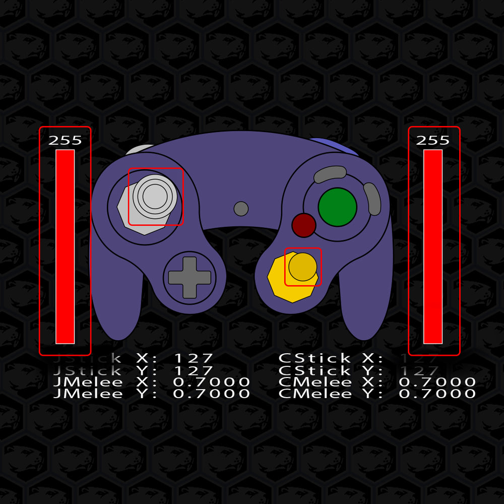
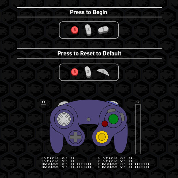
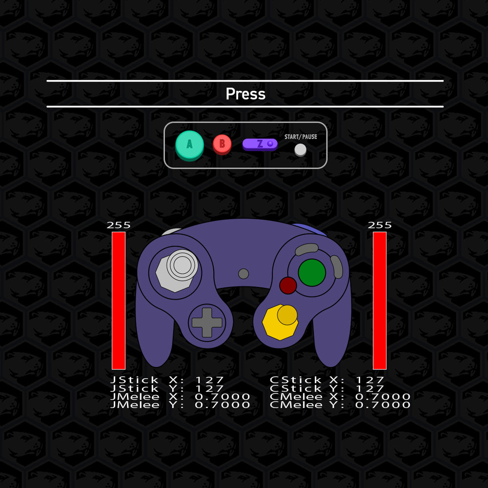
Safe Mode / Calibration / Soft Reset
Both sticks and triggers will be held for a few moments

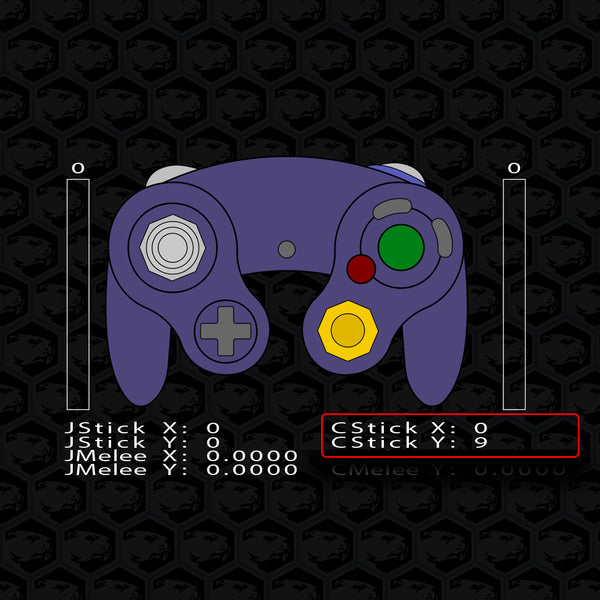
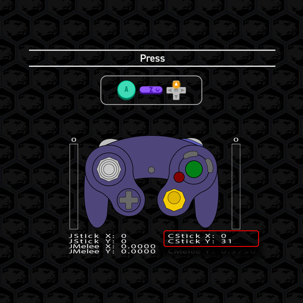
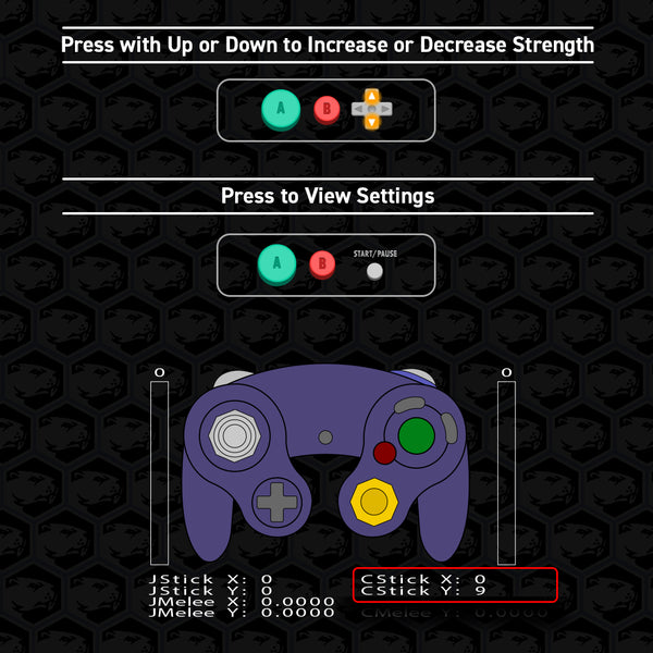
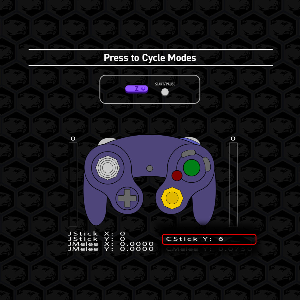
Controller Vibration Settings
The C-Stick y-axis will display the setting value for a few moments
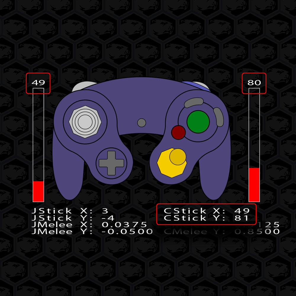
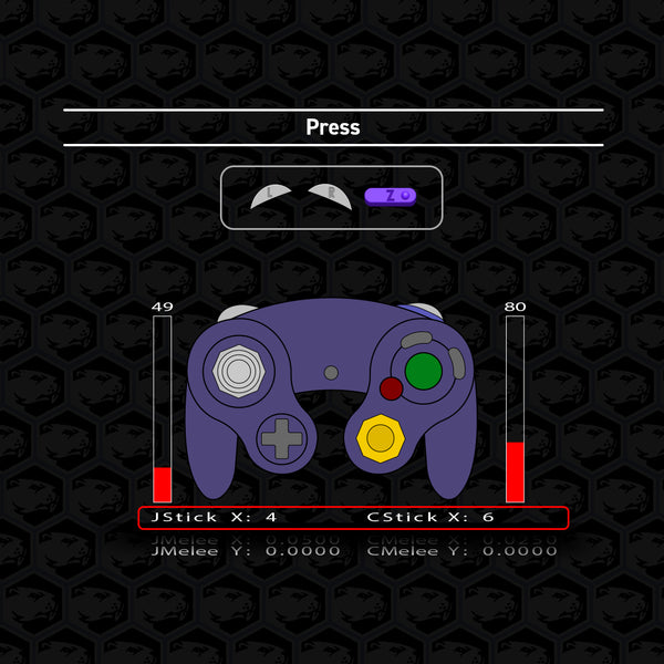
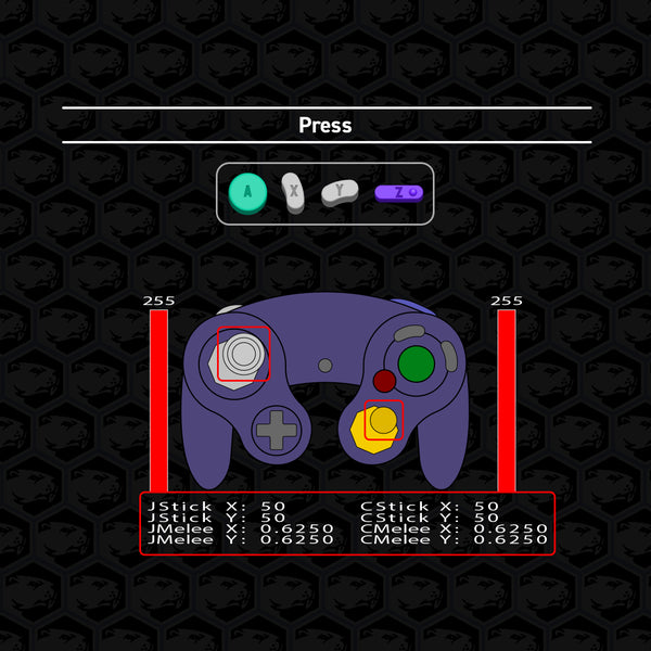
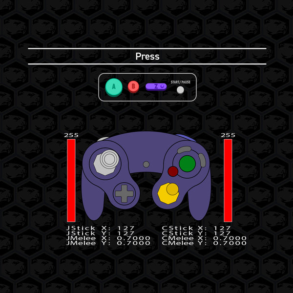
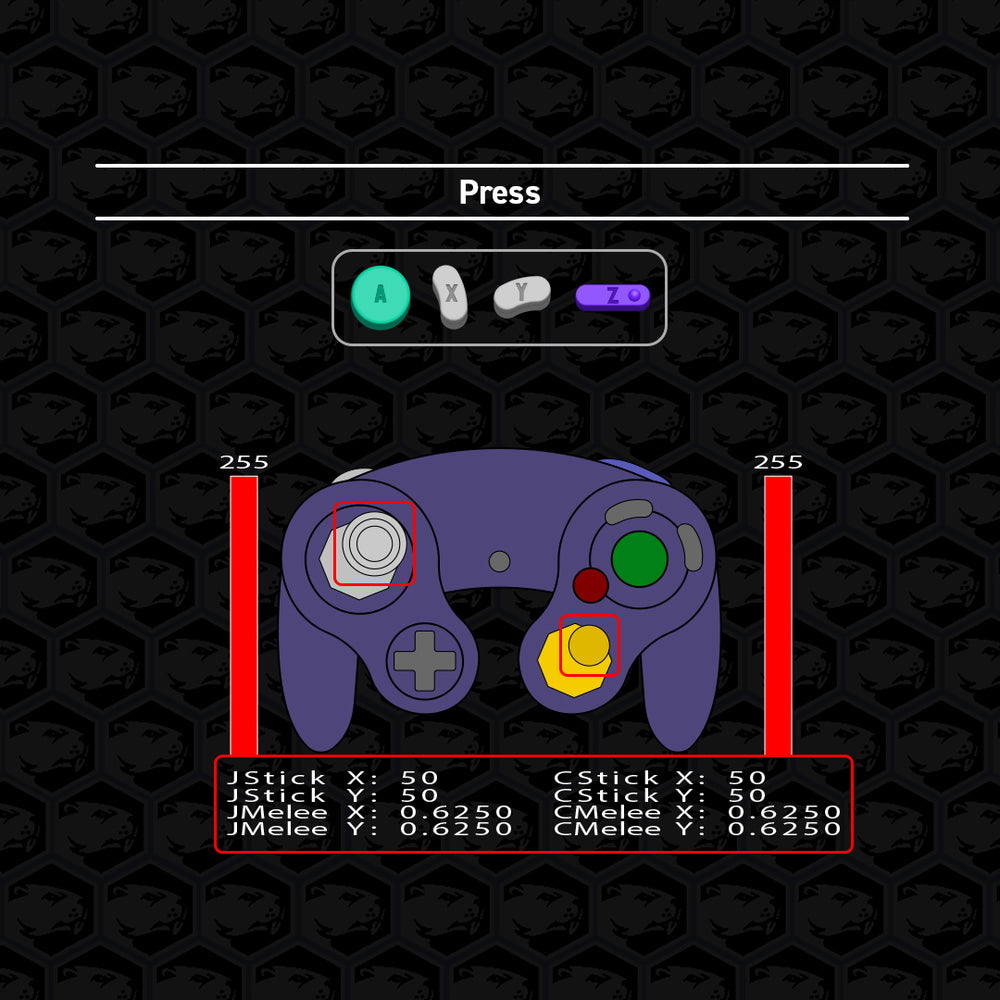
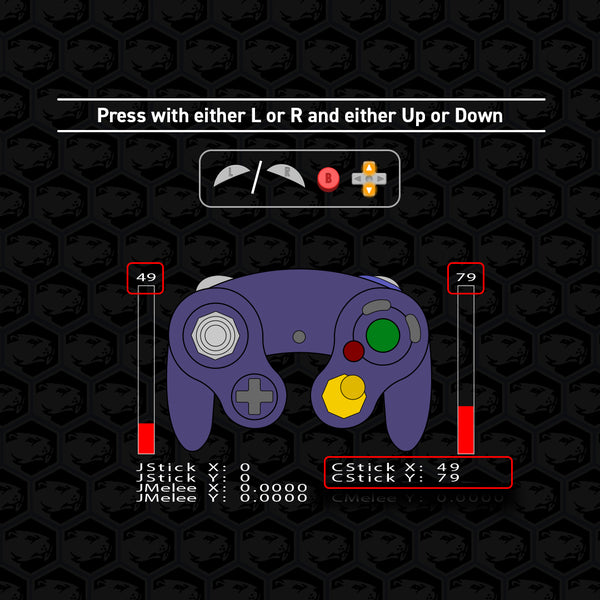
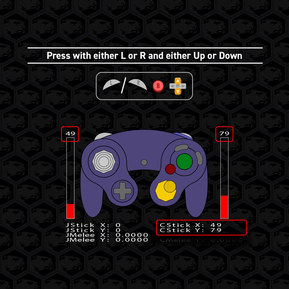
Set Analog Trigger Value
The analog trigger values (shown above the red bars) and C-Stick x-axis & y-axis will very quickly display the current setting
Viewable Settings
The following button combinations will allow you to look at the corresponding settings when safe mode is off.


| Table of Contents
| Check Firmware Version
| Controller Vibration Settings
| Left & C-Stick Filters
| Trigger Mode

Check Firmware Version
Viewable in the C-stick Y-axis.
Current public firmware: v0.31.
(Information is specified for this version)
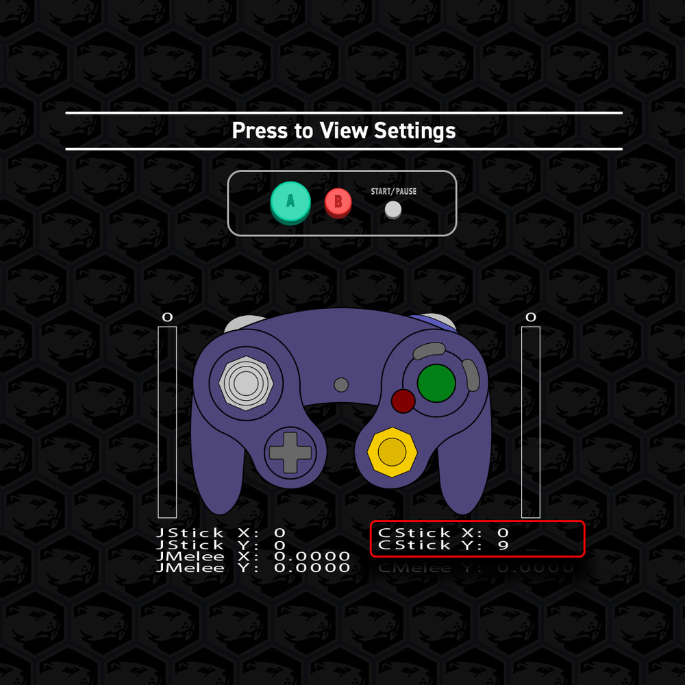
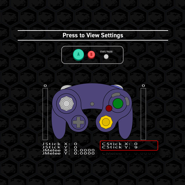
View Controller Vibration Settings
Viewable in the C-stick Y-axis
Settings range from 0 to 11.
The default is set to 9.
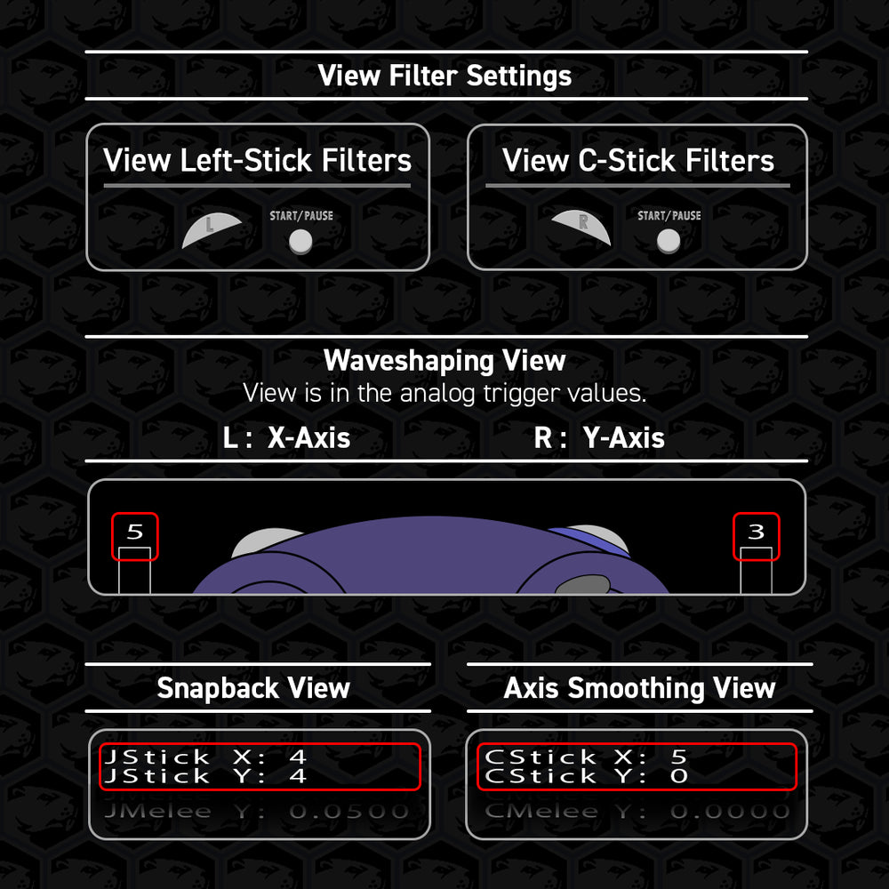
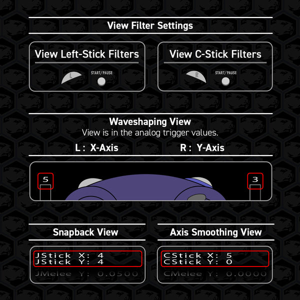
View Left Stick & C-Stick Filters
View each stick one at a time.
Snapback is viewable in the Left Stick values
Axis Smoothing is viewable in the C-Stick values
Waveshaping is viewable in the L & R analog values for the X-axis & Y-axis, respectively.

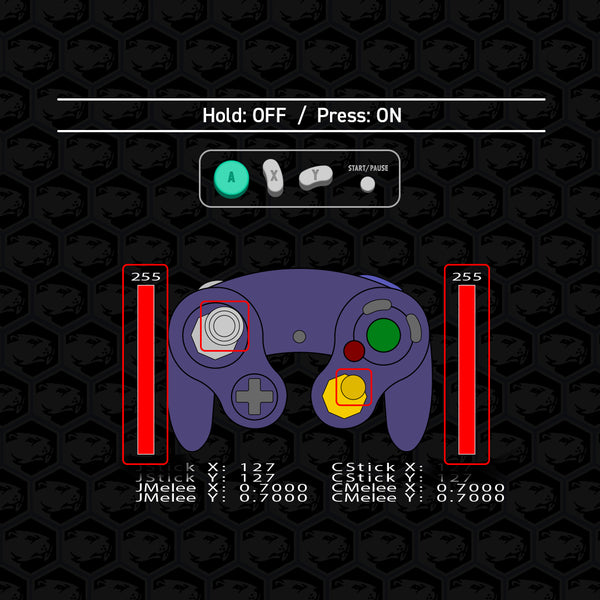
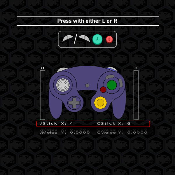
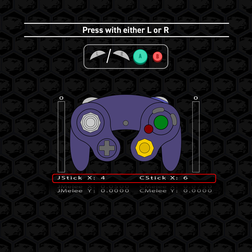
View Trigger Mode
Viewable in the Left Stick X-axis and C-Stick X-axis for the Left & Right Trigger, respectively.
The Set Analog Trigger Value for each trigger will also be displayed.
Getting Started
By default, the controller will lock the analog sticks to center every time you plug in.
Press B to activate control of the analog sticks.
Safe Mode will always be ON when plugging in the controller.
Below, we’ll go over a few quick settings.

| Table of Contents
| Toggle Safe Mode
| Auto-Initialize
| Soft Reset
| Controller Vibration Options
| Full Button Swap Remapping
| Tournament Modes
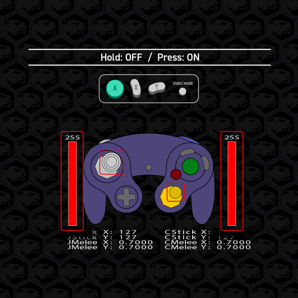
Toggle Safe Mode
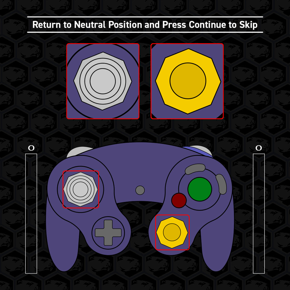
OFF: A 1 second freeze confirmation will occur. Release all buttons once you see the confirmation as shown in the image. Enables all Phob commands.
All changes made are saved once control returns to normal.
ON: A 3 second freeze confirmation will occur. Disables all Phob commands. Unplugging the controller will also resume Safe Mode.
Toggle Auto-Initialize
Make sure all sticks and triggers are in the neutral position when plugging in.
ON: Analog sticks will now activate automatically upon plug in.
OFF: Analog sticks will now only activate by pressing B upon plug in.
NOTE: The opposite position of the sticks will appear when toggling off. The values will also show negative numbers instead.
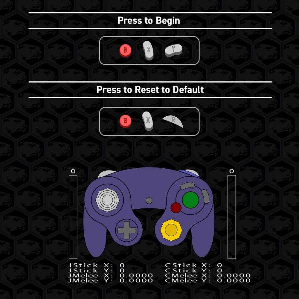
Soft Reset
Returns all modified settings to default.
Analog sticks retain the most recent calibration.
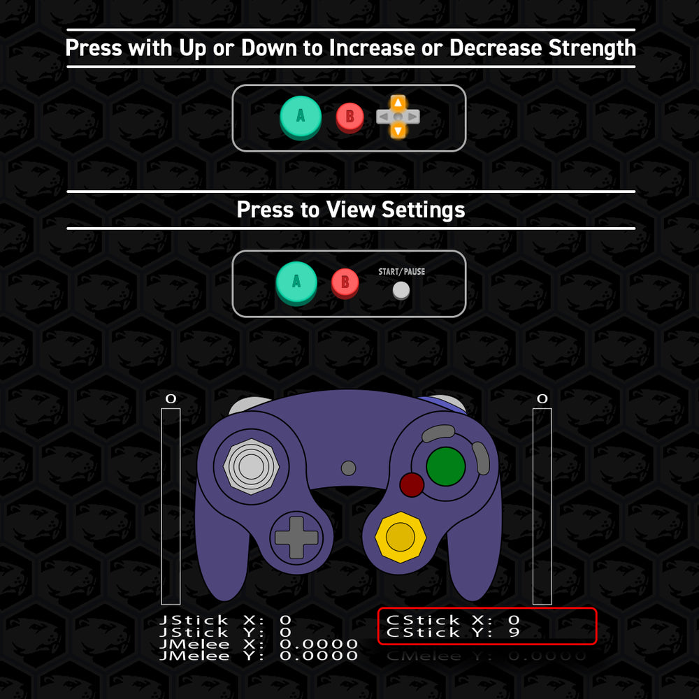
Controller Vibration Setting
Increase or decrease the strength of the controller vibration motor.
Settings range from 0 to 11.
The default is set to 9.
Set to 0 to disable vibration.
Full Button Swap Remapping
The Phob supports remapping A, B, D-pad Up, L, R, X, Y, and Z. Start the remap command, then press the buttons you want mapped in this order:
A → B → D-pad Up → L → R → X → Y → Z
This alphabetical order fills all 8 slots and exits after Z.
For example, to swap only two buttons, like Y and Z, start the command and press:
A B Du L R X Z Y
Each button can only be used once.
Remapping to L or R uses only the digital input.
If L or R is mapped to a face button, using Trigger Mode 5 or 6 is recommended.
Remapped buttons do not change Phob commands or LRAStart.
Tournament Modes
To prevent accidental D-pad Up and Start inputs, users can cycle through 6 simple modes that modify their input methods.
To bypass Tournament Mode, hold the button you want to use (Start or D-pad Up) then press the other button. Only the held button will activate.
- Default
- Hold to use D-pad Up
- Disable D-pad Up
- Hold to use Start
- Hold to use D-pad Up and hold to use Start
- Disable D-pad Up and hold to use Start
Trigger Configurations
The triggers on the gamecube controller are fairly customizable. By default, each trigger consists of both a slider (potentiometer) that registers analog values by how far down you pull the trigger and a separate contact press that registers a digital input at the bottom click.
Users can cycle through 9 different modes as well as button swap remappings to find a combination that best fits their playstyle. Users can also define a set analog value for use in modes 4 through 9. The default is set to 49. See Set Analog Trigger Value Adjustment further below for more information.
| Table of Contents
| Trigger Modes P1 - P3
| Analog Trigger Value Adjustment
Trigger Modes - P1
Mode 1 - OEM
Default
Mode 2 - Digital Only
Disables the analog slider input. Use this mode to improve Powershield success in SSBM.
Mode 3 - Analog Only
Disables the contact press and digital input. (Can still use the L + R + A + Start command to quit out in your favorite Smash game)
Trigger Modes - P2
Mode 4 - Limited Analog
The analog values will behave normally but not go beyond the “set analog trigger value”. Normal digital input on contact press.
Mode 5 - Analog on Contact Press
The contact press will register the “set analog trigger value” as the input at the bottom click. Disables the slider and digital input.
Mode 6 - Analog & Digital on Contact Press
The contact press will register the “set analog trigger value” and digital input simultaneously at the bottom click.
Trigger Modes - P3
Mode 7 - Hair Trigger Analog
The slider will register analog values with more sensitivity using a larger “set analog trigger value”.
Mode 8 - Limited Analog + Disabled Digital Press
The analog values will behave normally but not go beyond the “set analog trigger value”. Disables the digital input on contact press.
Mode 9 - Extreme Hair Trigger Analog
This mode is 2.5x more sensitive than mode 7. Designed for users with trigger plugs or similar short travel distance before the contact press.
Set Analog Trigger Value Adjustment
Trigger Modes 4–9 utilize this value and can be adjusted as needed.
Default is set to 49 at the lowest and can be increased up to 227.
Trigger Modes 7 & 9 adjusts the sensitivity by the set value, respectively:
49 = 1x or 2.5x | 140 = 2x or 5x | 227 = 3x or 7.5x
Smash game specific notes
Melee:
49 = largest lightshield | 140 = virtual max
Airdodge, Powershield, and Teching only activate with the digital input.
Ultimate:
79 = shield activation threshold
78 and below will not register anything
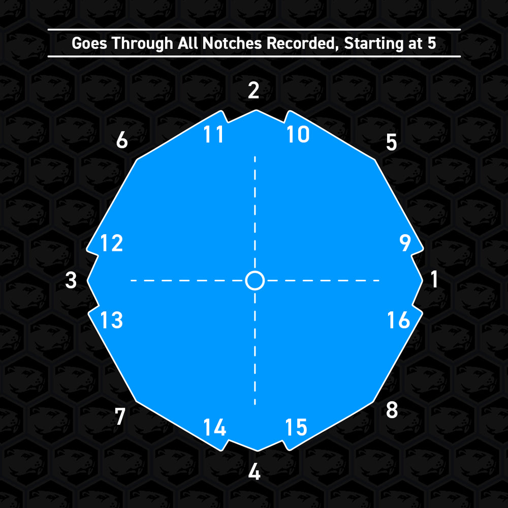
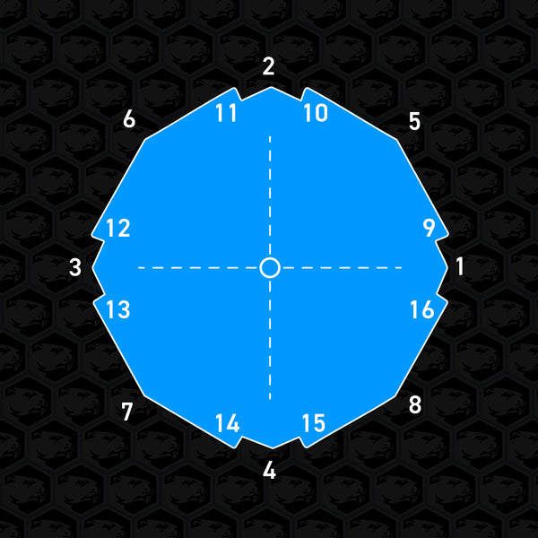
Analog Stick Calibration Steps
Users can calibrate the analog sticks for an accurate measurement of the control stick gates for their specific controller. Below we will go over how to complete the process while referring to the input display for guidance. If your Phob controller was received fully built and works fine, it may not be necessary.
This process has a measurement phase to record the physical position of the notches (Steps 1-6) and an adjustment phase to further fine tune coordinate values (Steps 7-9).
To begin, choose a stick to calibrate and follow the instructions below.
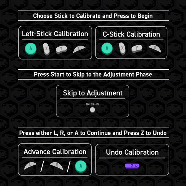


Button Combinations For Calibration
Familiarize yourself with the following button combinations to progress through the calibration process.
Begin by selecting a calibration option (Left-Stick or C-Stick).
After the freeze confirmation, the opposite stick will now guide you by displaying the current stick position being measured on the screen.

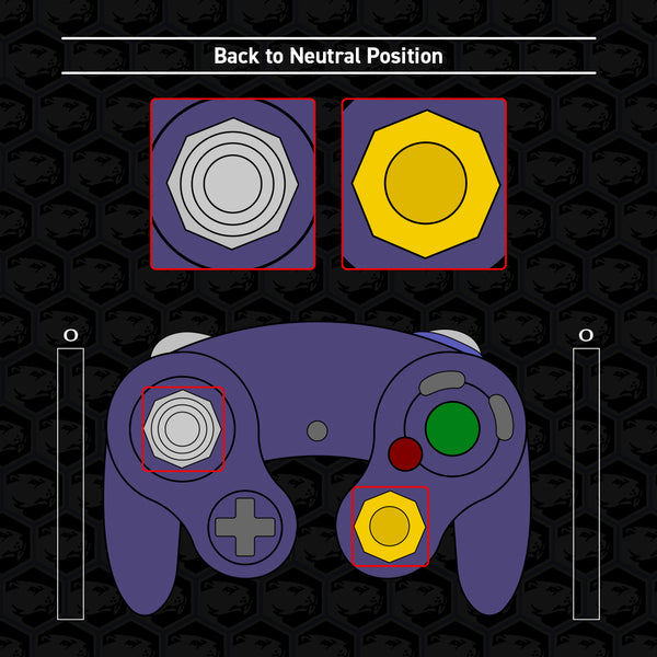
We start with the stick centered, then press continue. (You may have to press continue 1 extra time to proceed to the next position)
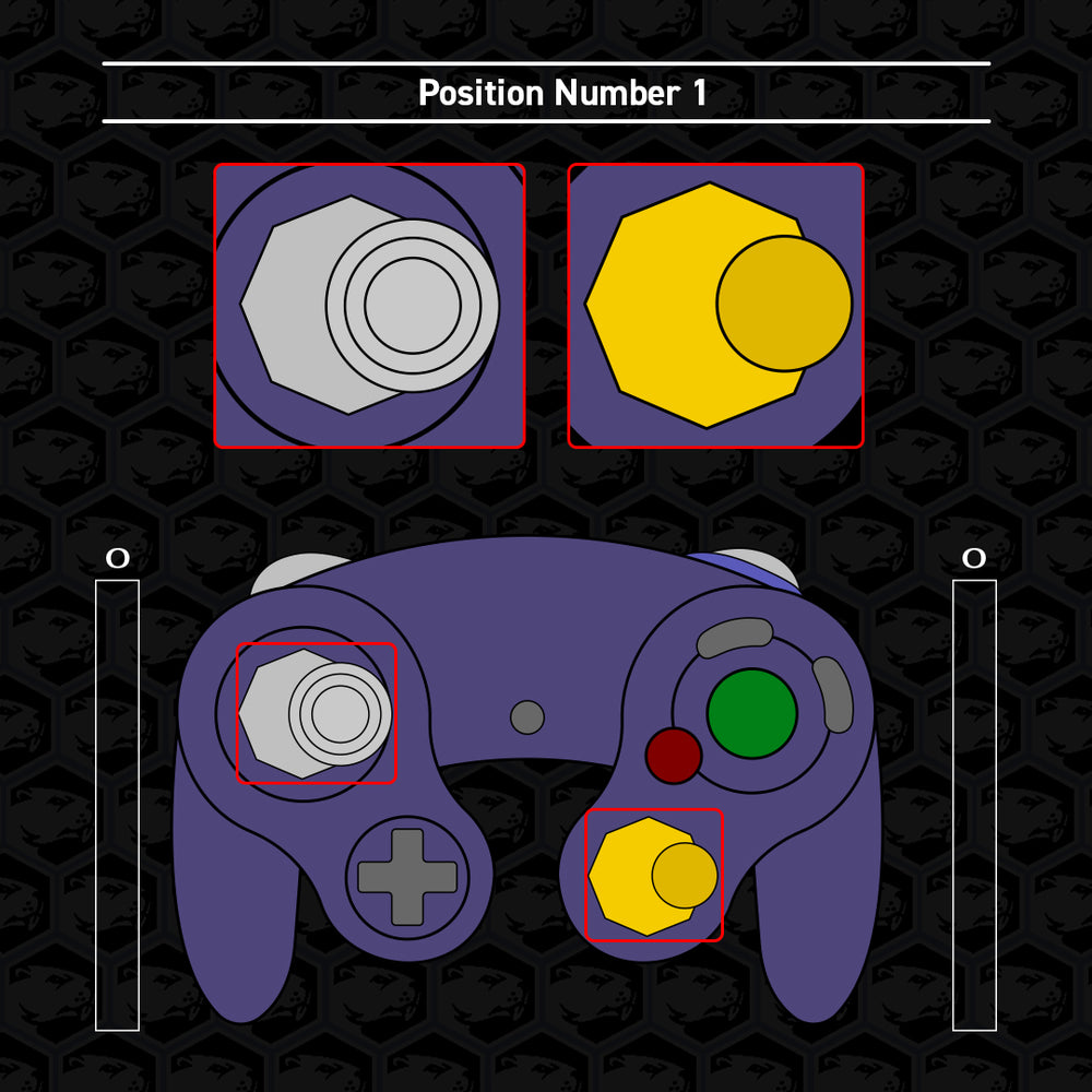
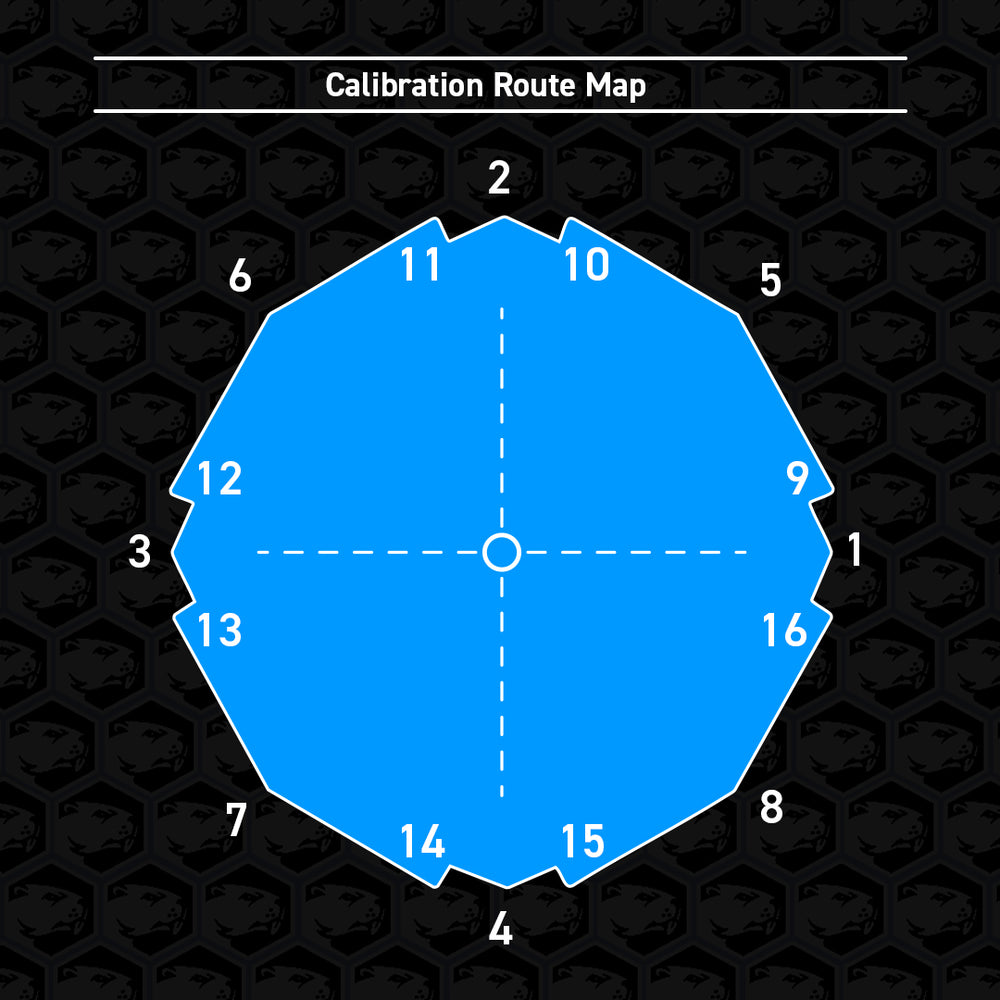
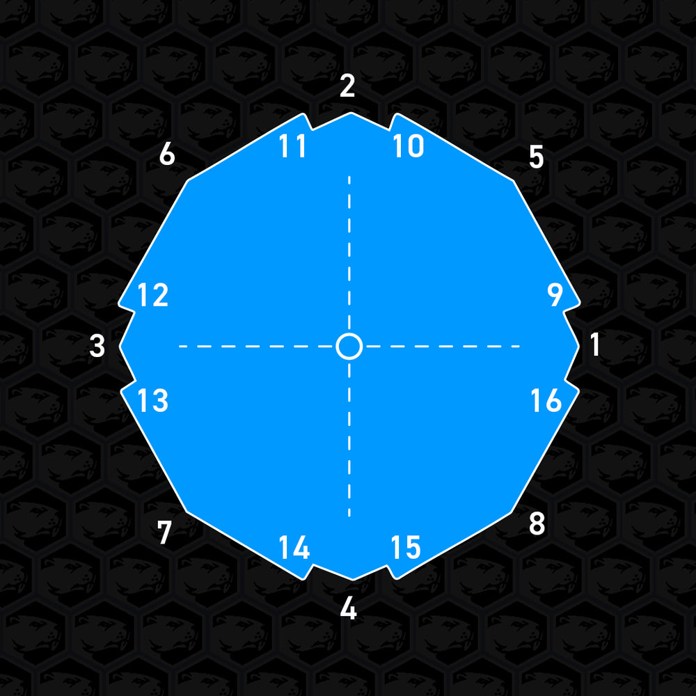
Once the guide shows the next position (The first notch we measure is to the right), move and HOLD the stick you’re calibrating to match with the guide, then press continue to record the measurement.
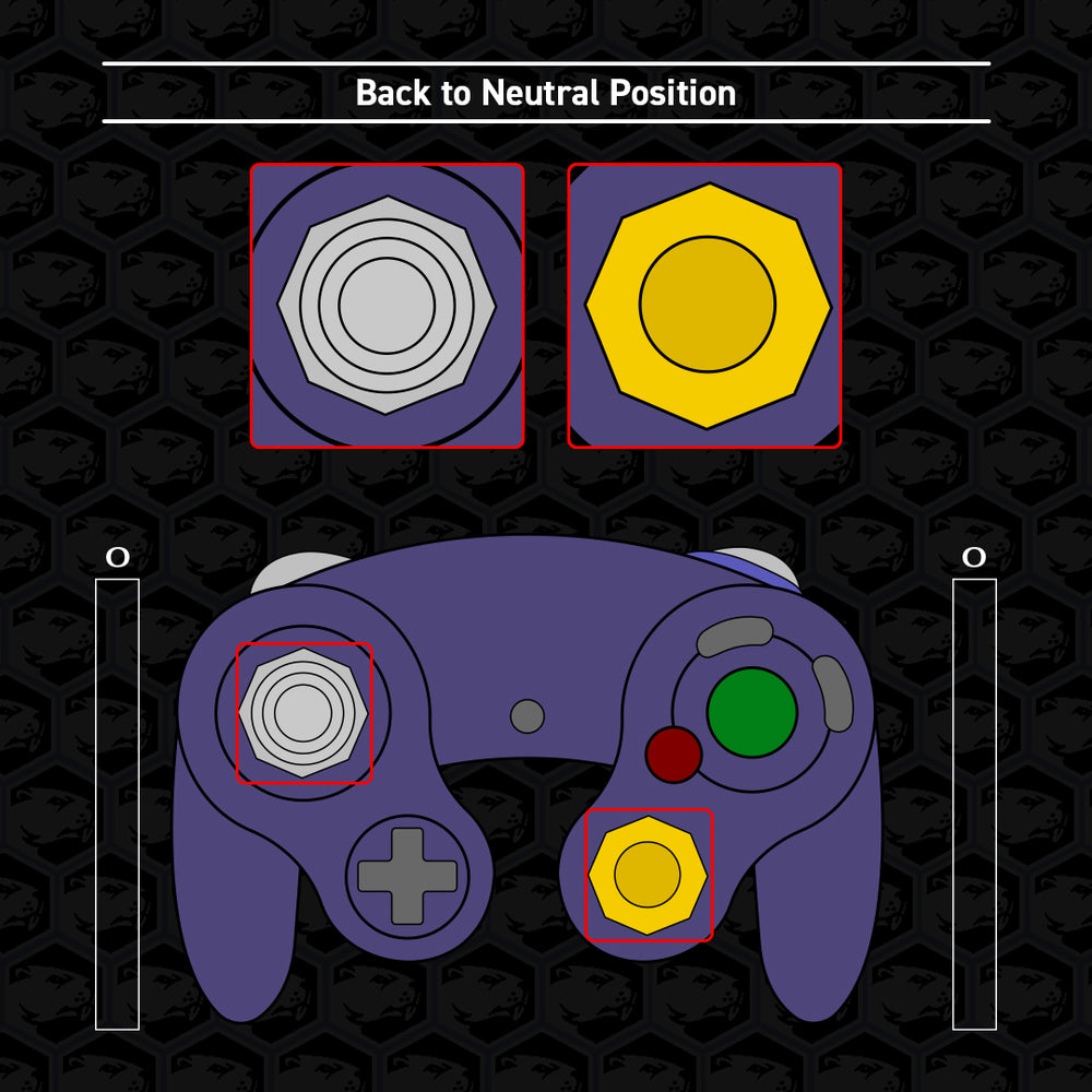
The guide should return to neutral, release the stick just as the visual guide presents, then press continue. Reminder to only press continue when the guide and your held stick position match.
Keep matching the guide and pressing continue through the measurement phase, alternating between holding the stick to the notch and releasing to center.
(The calibration route map around the stick gate can be seen in the diagram.)

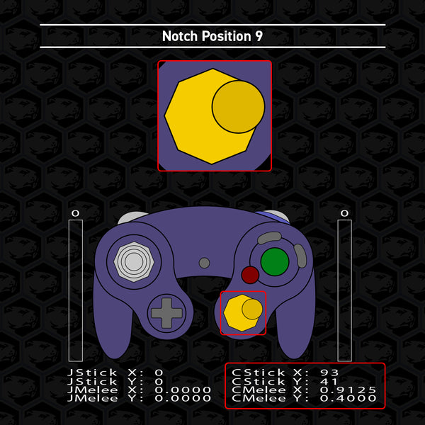
Stop once you reach notch position 9. The following 9 through 16 positions are the additional notches. (such as “firefox notches”)
If you only have some additional notches, see step 6. If you have all 8 additional notches and wish to record them for calibration, proceed as normal and continue to step 7.
If you only have a few additional notches (such as “wavedash notches”) or no extra notches at all, leave the stick released in the neutral position and press continue to skip each notch you do NOT have, and take care to record the notches you DO have.
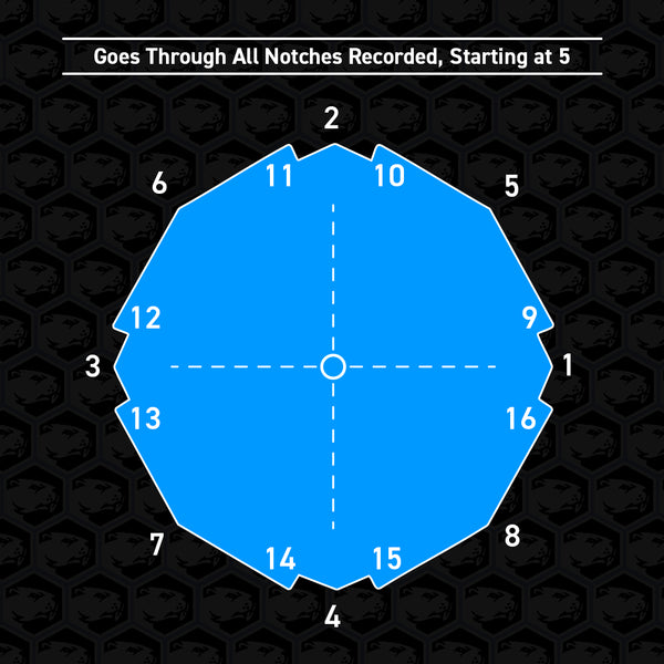
Once you have gone through all 16 notch positions or by pressing Start to skip measuring entirely, the guide will immediately move to the top right notch (position 5).
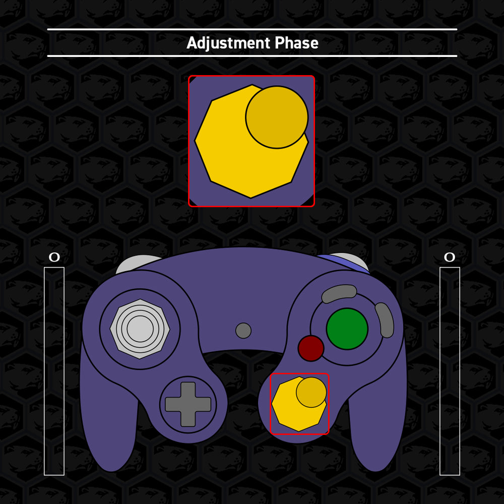
This is now the adjustment phase of the calibration process and should now have normal control of the stick you are calibrating.
The guide will show which notch is currently being adjusted. Hold the stick to that notch to view changes made in real time.
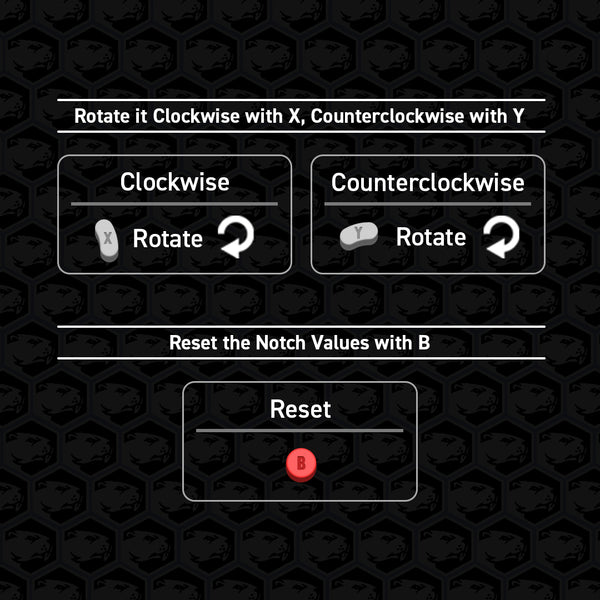
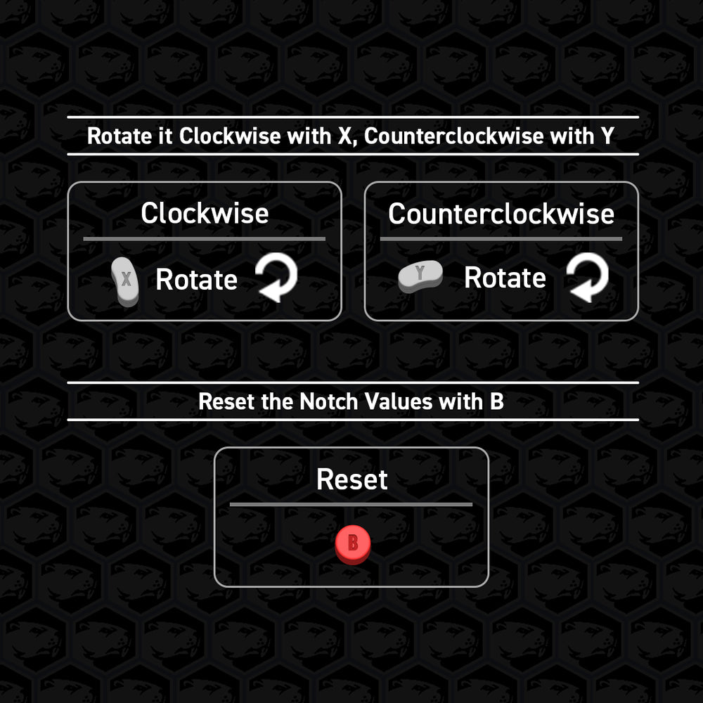
If you wish to adjust the recorded values, you can press X or Y to move it clockwise or counterclockwise, respectively, around the gate.
NOTE: There is a limit to how far you may adjust notch values.
Press B to reset the notch values.
Press continue when you are satisfied with the recorded values.
The guide will then proceed through all notch positions the Phob has recorded, not including the first 4. Press continue when satisfied.
Note:
If it skips a notch you believe you have measured, there is a problem and you may have to start over. If it persists, there may be an internal issue.
For recommendations on notch values, see the next section.
After pressing continue on the last notch position recorded, the guide will cease and the calibration process is finished.


Recommended Notch Values
These are optional adjustments that may benefit most players. Find what works best for you. For best results, repeatedly move the stick to the notch from many different directions as you are making adjustments to visualize the range you are working with.
Remember, the X and Y buttons rotate the coordinate values; they don’t simply increase or decrease the values. Please keep in mind which axis and direction we are referring to when applying these adjustments. Become familiar with the Cartesian (x-y) Coordinate Plane to understand how the values from the analog sticks are read. Negative values increase by moving the stick x-axis left and y-axis down while positive values increase by moving the stick x-axis right and y-axis up.
Most of these tips are for SSBM, but we have also included a tip for SSBU.
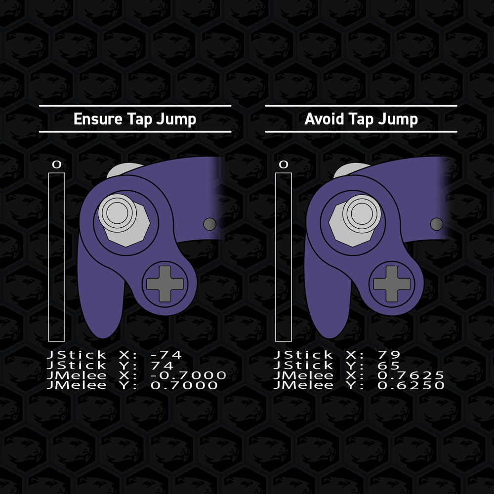
Left Stick - Upper Diagonal Notches
Ensure Tap Jump
y ≈ 0.7000
y = 0.6625 is the threshold for inputting Tap Jump.
or
Avoid Tap Jumps
y ≈ 0.6250
Allows using the upper notches without risk of accidentally jumping. Lowering this value may also help some players with performing unbuffered Up Tilts by a small margin.

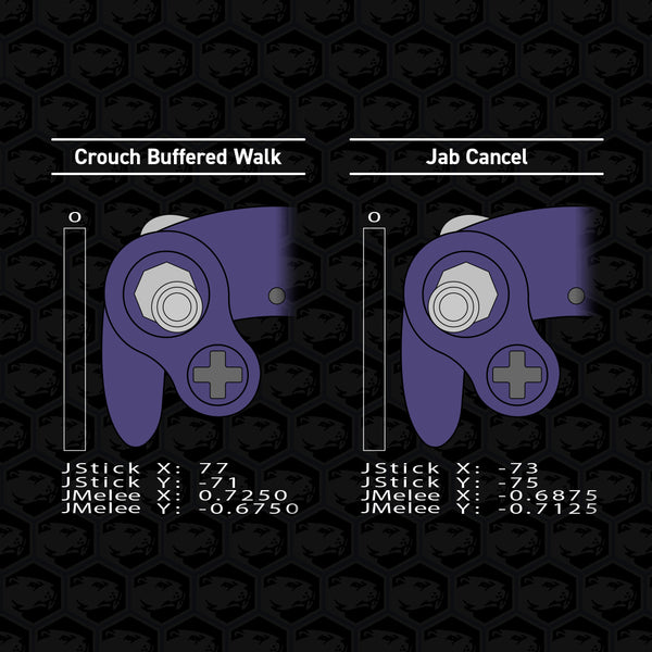
Left Stick - Lower Diagonal Notches
Crouch Buffered Walk
y ≈ -0.6750
To ensure Shield Drop accuracy, avoid y ≤ -0.6500. This notch value allows players to walk forward and instantly crouch once hit to more easily counterattack.
or
Jab Cancel
y ≈ -0.7125
This notch value allows some characters to be able to continuously use Jab1 while preventing the follow-up Jab sequence. If facing right, hold down-left.
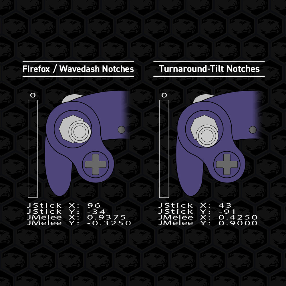
Left Stick - Additional Notches
Firefox / Wavedash Notches
Axis closest to center ≈ ±0.3250
To ensure execution accuracy, avoid values ≤ ±0.2750. These are the additional notches, 9 through 16.
or
Turnaround-Tilt Notches (SSBU)
Axis closest to center ≈ ±0.4250
To ensure execution accuracy, avoid values ≤ ±0.3875. These are the additional notches, 9 through 16.
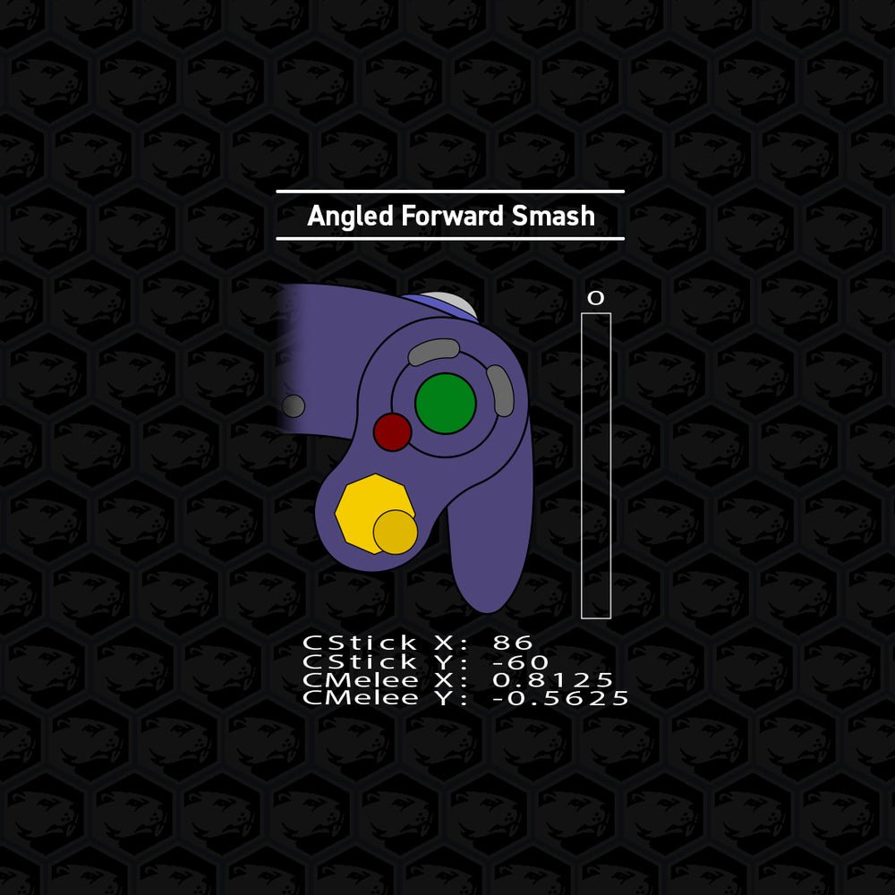
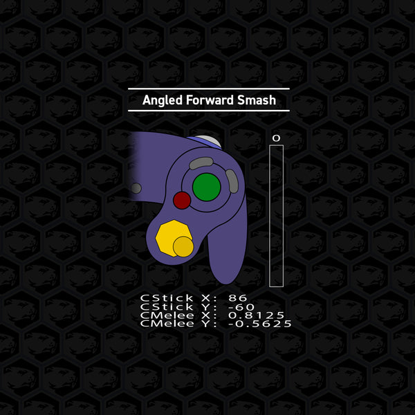
C-Stick - All Diagonal Notches
Angled Forward Smash
x ≥ ±0.8000
This value is at the limit of the adjustable range, and maxing it out is common.
If your adjustments won’t reach, try recalibrating for better results.
Avoid x ≤ ±0.7875 or y ≤ ±6500.
This is a deadzone and will not input anything.
Analog Stick Filters
These filters allow advanced users to further fine tune the responsiveness and behavior of their analog sticks. We do not recommend adjusting these filters without an input viewer. Most users may not need to modify these filters if the controller is behaving as intended. Below we will explain what each filter does and how to adjust them. Most filters can be applied to the X-axis and Y-axis.


| Table of Contents
| View Settings
| Snapback
| Wave Shaping
| Analog Stick Scaling
| Cardinal Snapping
| Axis Smoothing
| Raw Sensor Output
| Recommended Filter Settings
View Settings
Input these commands to see the corresponding analog stick filter settings.
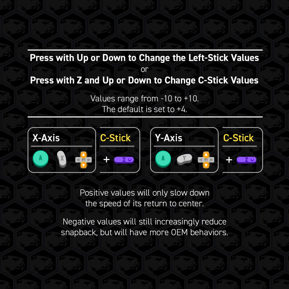
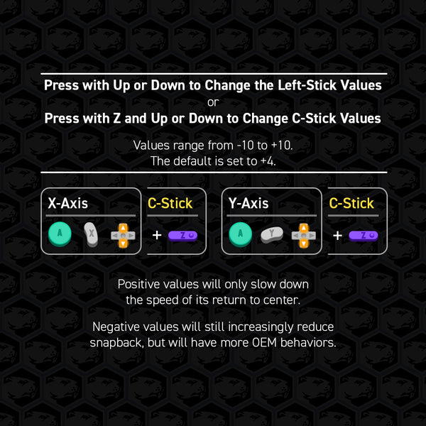
Snapback
This filter avoids the natural stick bounce when flicking the stick that may register in the opposite direction, aka snapback.
Values range from -10 to +10.
The default is set to +4.
Set to 0 to disable the filter.
Positive values will only slow down the speed of its return to center. Negative values will still increasingly reduce snapback, but will have more OEM behaviors.
The C-Stick version of this filter is treated the same as Axis Smoothing, refer there for details.
Pro Tip: to reduce the chances of getting the wrong move, try increasing the value on the axis you don’t want and decrease the value on the axis you do want.
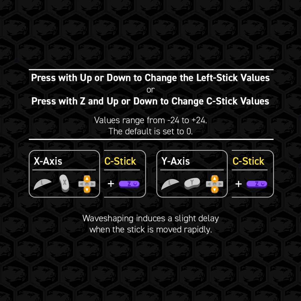
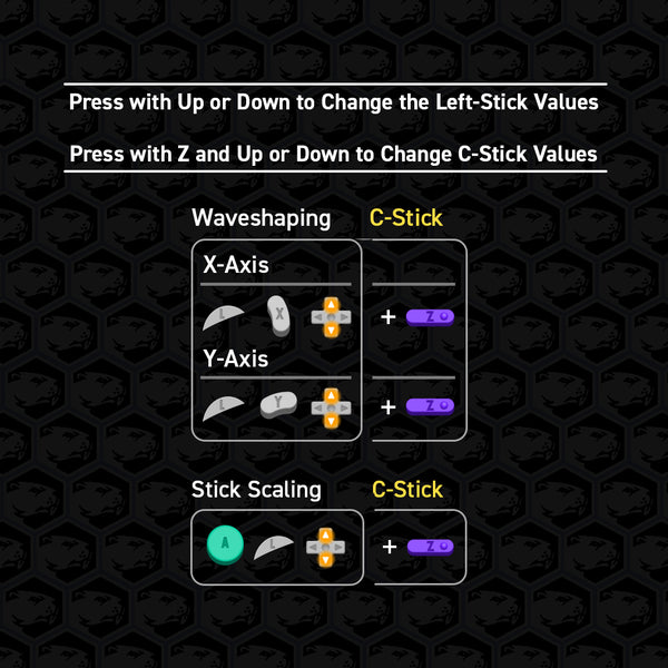
Waveshaping
This filter allows quick flicks of the analog stick to feel more responsive and effective, such as pivots, dashback, and stick tap short hops. Waveshaping induces a slight delay when the stick is moved rapidly.
Increasing this filter (further from 0) will sharpen motions by moving the delay later.
Values range from -24 to +24.
The default is set to 0.
Positive Waveshaping values provide a mild effect.
Negative Waveshaping values provide a strong effect.
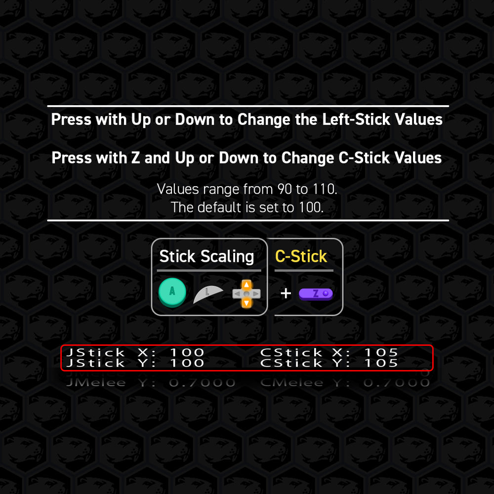
Analog Stick Scaling
This filter changes what range of values get registered at the edge of the control stick gate. Simply, Smash/Tap/Dash stick inputs will become more sensitive at higher values and less sensitive at lower values.
Values Range from 90 to 110.
Default is set to 100.

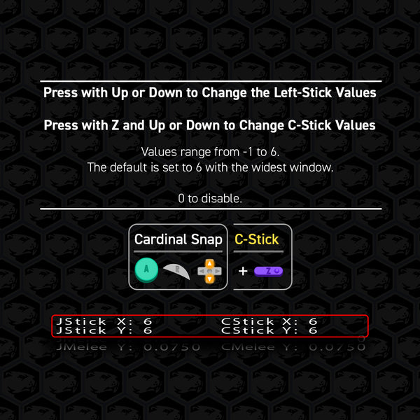
Cardinal Snapping
This filter will allow users to more reliably “snap” into the 1.0 cardinal directions. Users should note that standard OEM controllers will very normally top out at 0.9875 and be virtually negligible from 1.0 behavior. However, this feature can allow a wider window to lock into the cardinal.
Values range from -2 to 6.
Default is set to 6 with the widest window.
Set to 0 to disable the filter.
-1 will instead max out at 0.9875 by snapping 1 unit away. (for Melee Zelda teleports)
-2 will instead max out at 0.9875 by snapping to 7 units away.
The C-Stick version of this filter does not include a -2 value.
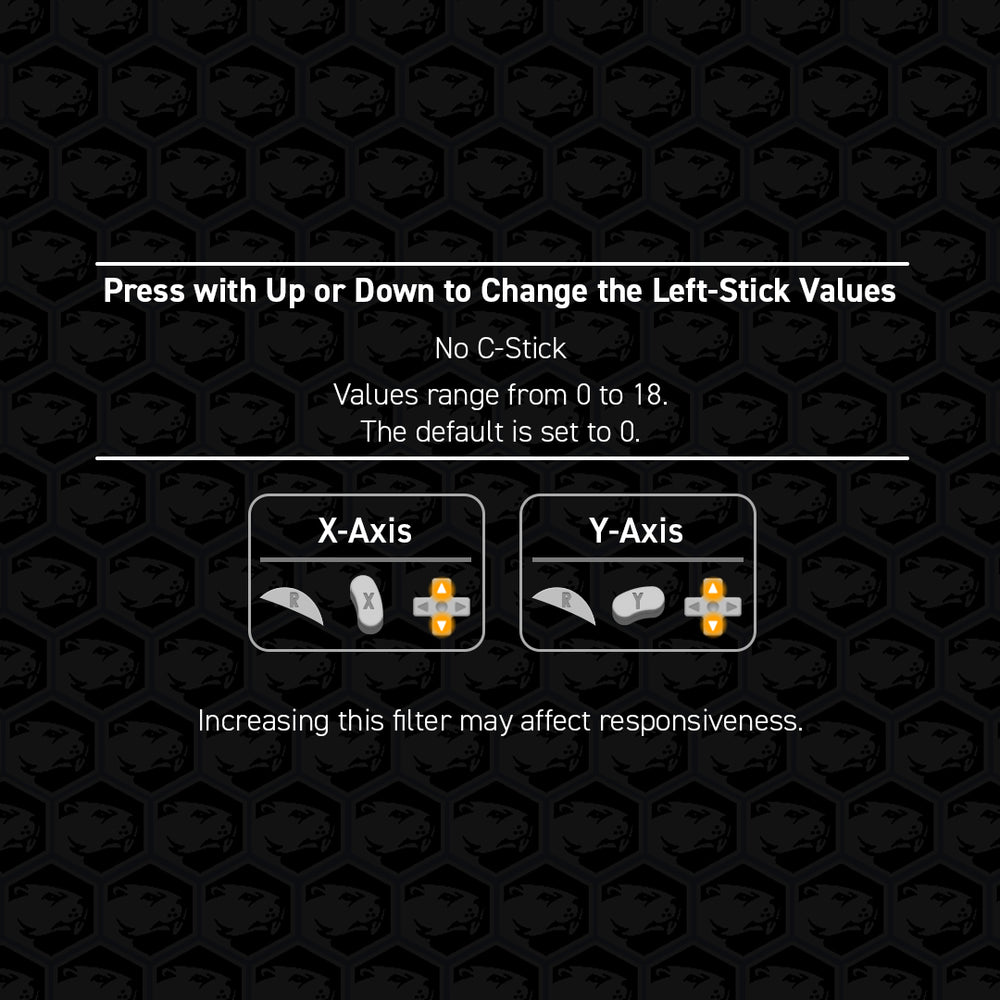
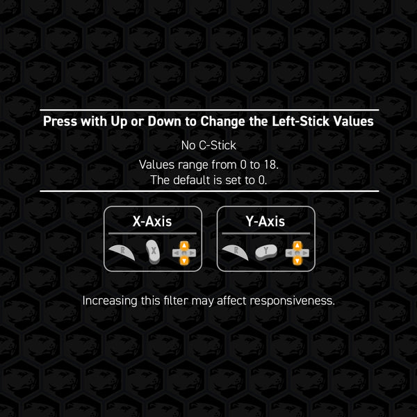
Axis Smoothing
Use these details for C-Stick Snapback
This filter works similarly to the widely used capacitor fix on OEM controllers to suppress snapback.
We do not recommend using both this filter and Snapback for the same axis on the analog stick.
Increasing this filter may affect responsiveness.
Values range from 0 to 18.
The default is set to 0.

Raw Sensor Output
This is a diagnostic feature to view your stick’s raw output before it is processed by the stick calibration.
If you feel your stick calibration was done correctly but are getting odd stick outputs, this can help get closer to the issue.
With the sticks centered, you should be close to 50. When moving the stick, the raw output should only change by about 10 units in each axis.
Depending on your Phob motherboard version, these values can vary. Please refer to original documentation at the bottom of the page for more details.

Recommended Filter Settings
These are optional adjustments that may benefit most players. Find what works best for you.
Left-Stick Single Motion Ledgedash (SSBM)
Increase Waveshaping x-axis to around 5+.
Allows players to let go of the ledge first and then immediately drift inward with just a straight down-forward motion into the diagonal notch.
Reliable C-Stick
Increase Analog Stick Scaling to around 105+.
Effectively widens the deadzone to more reliably input the desired direction.
Ready to go Controllers
Ready to skip the build process? These GameCube controllers come pre-built with drop-in phobs already installed, giving you the crisp performance upgrade right out of the box.
Want to explore even more drop-in options? Tap the button below to check out our full collection.